Dental implants are expected to transfer occlusal loads to the surrounding bone tissue while maintaining the mechanical stability of the implant–abutment–crown assembly. Conventional implants are mostly titanium-based, which provides high strength and corrosion resistance. However, the relatively high rigidity of titanium can reduce mechanical stimulation in the adjacent bone and, in some scenarios, contribute to stress/strain shielding concerns. For this reason, the common rationale behind composite design is "stiffness matching": when implant/abutment rigidity is brought closer to that of bone, load sharing can become more "physiological," particularly in the crestal cortical region, where signs of overloading or shielding tend to concentrate.
1. Introduction
Dental implants are expected to maintain mechanical stability of the implant–abutment–crown assembly while transferring occlusal loads to the surrounding bone tissue. Conventional implants are predominantly titanium-based, which provides high strength and corrosion resistance. However, titanium's relatively high stiffness can reduce mechanical stimulation in neighboring bone and may contribute in some scenarios to stress/strain shielding concerns. For this reason, a common requirement of composite design is "stiffness matching": when implant/abutment stiffness is brought closer to bone, load sharing can become more "physiological," particularly in the crestal cortical region where overloading or shielding effects frequently concentrate.
Finite element studies have explicitly examined hybrid Ti–PEEK implants as a strategy to reduce stiffness mismatch and its biomechanical consequences. In parallel, PEEK and fiber-reinforced PEEK variants are being studied as metal alternatives for implant and/or abutment, aiming to alter peri-implant stress patterns while keeping component stresses within safe limits.
While many implant simulations report stress (e.g., von Mises) and strain, energy-based metrics provide additional interpretability: they show where mechanical work goes (implant, cortical bone, or cancellous bone), how strongly the load is "directed" across the interface, and how composite architecture changes the distribution. This article compiles an energy-based framework for composite dental implant simulation under the following headings:
Strain energy and SED as descriptors of load transfer,
Effects of composite architecture (short fiber vs continuous carbon fiber reinforcement),
Interface integrity (osseointegration assumptions and debonding/contact modeling),
Stress reduction–deformation/fatigue sensitivity trade-offs under oblique loading.
2. Energy-Based Metrics in Dental Implant Biomechanics
2.1 Strain energy and strain energy density (SED)
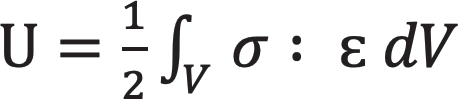
For a deformable body, elastic strain energy U represents the amount of work elastically stored under loading:
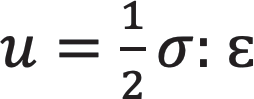
Strain energy density u is its local equivalent:
In implant biomechanics, SED can be interpreted as a practical proxy for the mechanical stimulus experienced by bone. As implant stiffness increases, the system may store more energy in implant components and leave less energy in bone; when stiffness decreases, energy can be redistributed toward the peri-implant region—but not always homogeneously. The practical value of energy reporting is its ability to physically meaningfully distinguish between "bone is loaded" and "bone is bypassed" patterns.
2.2 Energy routing and composite stiffness
Composites influence energy routing primarily through these mechanisms:
Elastic modulus: PEEK has lower stiffness than titanium; CFR-PEEK stiffness varies widely depending on fiber volume fraction/orientation/continuity.
Anisotropic properties: CFR-PEEK can exhibit orthotropic behavior when loaded along the composite's principal stiff axes.
Damping/viscoelasticity (optional): Polymer matrices can dissipate energy; most dental FEA assumes linear elasticity. If needed, analysis can be extended to viscoelasticity or time-dependent behavior.
The key insight from comparative studies is this: "composite" is not a single category; short-fiber CFR-PEEK and continuous-fiber CFR-PEEK can produce different patterns in the peri-implant region. For example, a 2024 FE study comparing different CFR-PEEK architectures found that short-fiber CFR-PEEK provided more uniform stress distribution around the bone–implant contact zone compared to titanium and had potential to reduce stress shielding/stress concentration tendencies.
2.3 Interface integrity as an energy problem
Beyond volumetric energy measures, implant success depends on bone–implant interface conditions:
Fully bonded interface: idealized "complete osseointegration," best-case stability,
Frictional contact: early stage or partial integration,
Debonding/contact evolution: more realistic approach.
A fundamental limitation of many simplified FEA models is the assumption that the interface is perfectly bonded everywhere. More realistic formulations using friction contact laws calibrated to experiments have been proposed to capture debonding in partially osseointegrated interfaces. In the energy-based reporting approach, interface integrity can be quantified not only by stress but by contact work, slip, debonding tendency, and micromotion thresholds.
3. Finite Element Workflow for Composite Dental Implant Assessment
This section presents a practical modeling route suitable for a thesis or SCI-level study comparing titanium with composite concepts (PEEK/CFR-PEEK, Ti–PEEK).
3.1 Geometry and components
A typical model includes:
Implant fixture and abutment (optional screw),
Crown (ceramic/metal-ceramic/composite),
Cortical and cancellous bone segments (mandible or maxilla depending on scenario).
Mesh refinement is particularly critical in:
Implant neck/crestal bone region,
Tooth–bone contact zone (thread–bone),
Abutment–implant connection.
3.2 Material models
Titanium is typically assumed to be linear elastic isotropic. PEEK and reinforced PEEK can be modeled at different levels of detail:
Linear elastic isotropic (preliminary screening),
Orthotropic for CFR-PEEK (recommended),
System-level variants (e.g., titanium implant with PEEK abutment) as a "design option."
A 2024 3D FEA comparison showed that switching between titanium and PEEK abutments could significantly alter stress distribution in the implant system and supporting bone.
3.3 Loading: vertical vs oblique occlusion
Dental implants rarely experience purely axial forces; oblique loads most often determine peak responses. Numerous studies emphasize that oblique loading can increase component stresses and alter bone loading patterns, making it an essential scenario in composite assessment. In CFR-PEEK–titanium comparisons, stress–strain trade-offs are most clearly seen here.
Recommended load cases:
Axial (e.g., 100–200 N),
Oblique (e.g., 30°–45°, similar magnitude),
Optional: parafunction/bruxism scenario (for sensitivity).
3.4 Interface conditions and osseointegration
At minimum, these two conditions should be compared:
Bonded interface: complete osseointegration, best-case stability,
Frictional contact: early stage or partial integration.
For higher realism, debonding/contact evolution can be added. Frictional contact formulations representing debonding in partially osseointegrated implants can be used to model progressive adhesion loss and tangential debonding.
3.5 Validation considerations
Where possible, FE predictions should be supported by experimental validation. A review focused on finite element contact analysis in dental/implant restorations emphasized the benefit of surface strain measurements in validating FE models and the critical nature of contact analysis as a technique.
4. Effect of Composite Materials in Dental Implant Systems
This section summarizes what composite substitution typically changes and how to report it using energy metrics.
4.1 Peri-implant bone: stress/SED redistribution (load-sharing effect)
Ti–PEEK hybrids: An FEA study of a Ti–PEEK composite implant compared different hybrid placements and showed that hybrid concepts—in scenarios with or without marginal bone loss—could alter the mechanical response in host bone compared to conventional titanium. When interpreted with energy metrics, these designs can be evaluated in terms of whether they increase SED/energy in peri-implant bone while creating local overloading.
PEEK / reinforced PEEK implants: Studies analyzing PEEK and reinforced PEEK implants report significant shifts in bone stresses and deformations compared to titanium. SED maps are particularly valuable here: two designs may show similar peak stress; however, the spatial pattern of SED can differ, meaning different remodeling stimulus distribution.
Reinforcement architecture matters: A 2024 FE comparison found that short-fiber CFR-PEEK produced more uniform stress distribution around the bone–implant zone compared to titanium, interpreting this in the framework of reducing stress shielding/stress concentration tendencies.
4.2 Implant/abutment components: stress may decrease while strain increases
A 2025 CFR-PEEK–titanium FEA reported that titanium implants could show higher von Mises stresses in the implant/abutment under oblique loading, while CFR-PEEK components could exhibit lower stress but markedly higher strain levels. The same study, pointing to more uniform stress distribution in peri-implant bone with CFR-PEEK and suggesting reduced stress shielding, cautioned about deformation-related risks and fatigue sensitivity.
Implication for energy reporting: Reporting peak von Mises alone is insufficient. It must be paired with:
SED maps in cortical crest and cancellous bone,
Maximum principal strain in components,
Total strain energy distribution (implant vs bone),
Interface micromotion/contact work.
4.3 Abutment material: a system-level composite option
Not every composite strategy requires a fully composite fixture. A 2024 FEA comparing titanium vs PEEK abutments showed that abutment material choice could influence stress distribution in the implant prosthetic system and surrounding bone. Energetically, this is a controllable lever: by shifting some of the compliance/damping to the abutment, the conventional titanium fixture can be preserved, thereby seeking balance between osseointegration confidence and load-transfer adjustment.
4.4 Interface integrity, partial osseointegration, and debonding
Composite designs that increase compliance may increase micromotion in early stages before osseointegration is complete. For this reason, realistic osseointegration assumptions are critical. Debonding-aware contact formulations offer a means to model partially integrated interfaces and their evolution under load.
4.5 Recommended "results package" for a composite dental implant study
To make composite effects clear and reproducible, report:
SED maps (cortical crest + cancellous): titanium baseline vs composite(s),
Energy distribution: U_implant, U_cortical, U_cancellous (axial/oblique),
Component safety: max von Mises + max principal strain (abutment, screw, neck region),
Interface stability: micromotion/contact slip; sensitivity to osseointegration level,
Architecture sensitivity (if CFR-PEEK): short-fiber vs continuous-fiber comparisons.
5. Conclusions
Energy-based modeling helps transform "composite material selection" into a mechanistic narrative: composites primarily adjust stiffness and anisotropy, thereby rerouting strain energy and SED between implant components and peri-implant bone. Findings from FE studies show that PEEK/CFR-PEEK and Ti–PEEK concepts can meaningfully alter stress/SED patterns in bone; however, benefits depend on reinforcement architecture, and particularly under oblique loading, there are trade-offs such as increased strain and possible fatigue sensitivity in more compliant systems.
Therefore, a sound composite implant paper should report stress metrics alongside SED/energy distribution, interface stability measures, and sensitivity analyses for bone quality and osseointegration level.
You can access the English version of the article via the QR code below. / Makalenin İngilizce versiyonuna aşağıda yer alan karekod üzerinden erişebilirsiniz.

Gallery